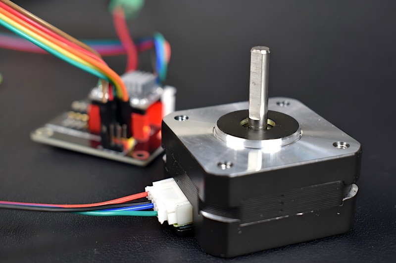
Electric motors known as stepper motors are frequently employed in applications requiring exact control over rotational position, speed, and direction. They are distinct from regular DC motors in that they move in discrete steps, providing finer control over the motor’s movement.
What is a Stepper Motor?

Each step is an angular rotation of the motor shaft, and the motor can be controlled to rotate by a set number of steps. These motors are designed to rotate a fixed amount, usually in the range of 0.9° to 1.8° per step, depending on the motor’s design.
The ability of stepper motors to achieve fine control without the requirement for feedback systems is its main benefit over other motor types (such as brushed DC motors). Stepper motors are typically controlled by sending a sequence of electrical pulses to the motor’s windings, with each pulse causing the motor to move one step forward or backward.
Types of Stepper Motors
Before diving into control techniques, it’s important to understand the different types of stepper motors, as they affect the way the motor is controlled:
Permanent Magnet (PM) Stepper Motors:
- With a permanent magnet in the rotor, these motors offer increased torque and efficiency at reduced speeds.
- They are the most common type of stepper motor and are ideal for low-speed applications.
Variable Reluctance (VR) Stepper Motors:
- In these motors, the rotor is made from soft iron, and the rotor’s movement is guided by the magnetic reluctance changes when the stator is energized.
- Compared to PM motors, they have a lesser torque but a better speed capability.
Hybrid Stepper Motors:
- These combine the characteristics of VR and PM stepper motors. High torque, accuracy, and speed are all balanced by them.
- Hybrid stepper motors are the most widely used in industrial applications.
Basic Principles of Stepper Motor Control
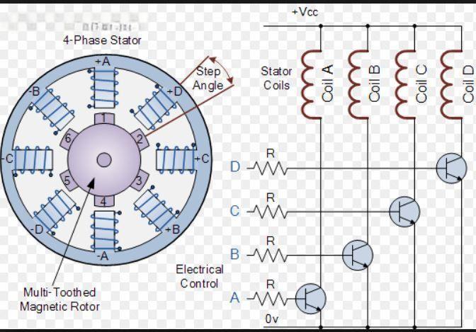
Stepper motors rely on a set of windings arranged in a stator to generate magnetic fields. Motion is created by the interaction of these fields with the rotor, or rotating component. Usually, with a permanent magnet or a piece of soft iron, the rotor moves incrementally as the stator windings are activated in a particular order.

There are several key concepts to understand in controlling a stepper motor:
Step Angle:
The step angle defines how much the rotor moves with each step. For example, if a stepper motor has a 1.8° step angle, the motor’s rotor will move 1.8° for each pulse.
The total rotation of the motor can be determined by dividing 360° by the step angle. For example, a motor with a 1.8° step angle would require 200 steps to complete a full revolution (360° / 1.8° = 200 steps).
Step Modes:
Stepper motors can be driven in different modes depending on how the coils are energized:
- Full Step: The motor is energized such that each step moves the rotor by the full step angle.
- Half Step: The motor moves in smaller steps, providing smoother movement and higher resolution.
- Microstepping: This is the most advanced mode, where the motor’s coils are energized in such a way that the rotor moves in very small increments. This provides very fine control and smooth movement.
Phase and Coil:
- A stepper motor consists of multiple phases or coils. By energizing these coils in the correct sequence, the rotor is forced to move incrementally.
- For instance, in a two-phase stepper motor, the rotor rotates in distinct steps due to the magnetic field created by the coils being energized in a particular order.
Methods of Controlling a Stepper Motor
There are several ways to control a stepper motor, each with its own advantages and disadvantages. The method you choose depends on the application, precision required, and the available hardware.
Using a Microcontroller (e.g., Arduino)
Stepper motors are frequently controlled by microcontrollers. They produce the required pulse signals that are transmitted to the driver circuit of the motor, which regulates the current passing through the coils of the motor. This technique is frequently applied to small machinery and do-it-yourself projects.
For example, an Arduino can control a stepper motor by using a library such as AccelStepper. The Arduino sends a series of digital pulses to the motor driver, and the driver supplies the appropriate voltage and current to the motor coils.
Basic Arduino Code Example:
#include <Stepper.h>
const int stepsPerRevolution = 200; // Change this to match your motor’s specification
// Initialize the Stepper library with the number of steps per revolution
Stepper stepper(stepsPerRevolution, 8, 9, 10, 11);
void setup() {
// Set the motor speed (in RPM)
stepper.setSpeed(60);
}
void loop() {
// Move the motor 100 steps forward
stepper.step(100);
delay(1000);
// Move the motor 100 steps backward
stepper.step(-100);
delay(1000);
}
Using a Dedicated Stepper Motor Driver
You may control the current flowing to the stepper motor coils using a specialized circuit known as a stepper motor driver, such as the A4988 or DRV8825. In addition to handling the higher currents needed by stepper motors, these drivers offer micro stepping capabilities for more fluid motion.
For example, an Arduino or other microcontrollers can be combined with a driver such as the A4988 to control the stepper motor through pulse signals. The microcontroller generates a signal, and the driver controls the motor’s coils according to that signal.
Basic wiring for an A4988 driver with an Arduino:
- VDD to Arduino 5V
- GND to Arduino GND
- STEP to an Arduino digital pin (e.g., pin 3)
- DIR to an Arduino digital pin (e.g., pin 4)
- VMOT to a motor power supply
- M0, M1, M2 pins for microstepping settings (optional)
Using a Computer or a PLC (Programmable Logic Controller)
For industrial and more complex applications, stepper motors can be controlled by a computer running control software or by a PLC. This setup is common in CNC machines and automated systems, where higher-level control is needed for multiple motors and precision movement.
Control with a Power Supply
In addition to drivers, the power supply is a key component in stepper motor control. The voltage and current specifications of the motor and driver must match, as improper power supply can cause overheating, loss of torque, and damage to the motor.
Control Signals and Timing
- Pulse Rate (Frequency): The frequency of the pulse signal determines the speed of the motor. Faster movement is associated with a greater frequency, whereas slower movement is associated with a lower frequency.
- Direction Control: For many drivers, the DIR pin controls the rotational direction. Changing the state of this pin (HIGH or LOW) will reverse the motor’s rotation.
Stepper Motor Control Summary Chart
| Control Method | Advantages | Disadvantages |
| Microcontroller | Low-cost, simple, easy to program | Limited power handling |
| Dedicated Stepper Driver | Reliable, handles higher power, microstepping support | More complex wiring, additional cost |
| PLC/Computer-based Control | High precision, scalable for large systems | Expensive, complex setup |
| Power Supply Control | Basic, works for simple applications | Limited functionality, no advanced control |
Key Considerations When Controlling a Stepper Motor
- Power Requirements: Stepper motors require more power than regular DC motors, especially when they are under load or operating at high speeds. To prevent damage, always use a power supply that is compatible with the motor’s requirements.
- Heat Dissipation: Stepper motors tend to get hot, especially under heavy loads. If your motor is running for extended periods, make sure it has proper ventilation or consider adding heat sinks or fans.
- Microstepping: While full stepping gives the motor its highest torque, microstepping offers smoother motion and better precision, albeit with reduced torque. When choosing your control approach, it is essential to comprehend the trade-offs.
Conclusion
Understanding the behavior of a stepper motor and choosing the best control strategy for your application is essential to controlling it. Whether using a microcontroller like Arduino, a dedicated driver like the A4988, or more advanced industrial systems, stepper motors provide excellent control over position and speed without the need for feedback systems. By choosing the right combination of power, drivers, and control signals, you can achieve precise and reliable operation for your project.
