Brushless DC (BLDC) motors have become integral to various applications due to their high efficiency, reliability, and long operational life. Because BLDC motors employ electronic commutation instead of physical brushes, they experience less wear and tear than their brushed counterparts.
A key aspect of BLDC motors is their speed, which is essential for applications like drones, industrial automation, and electric vehicles.
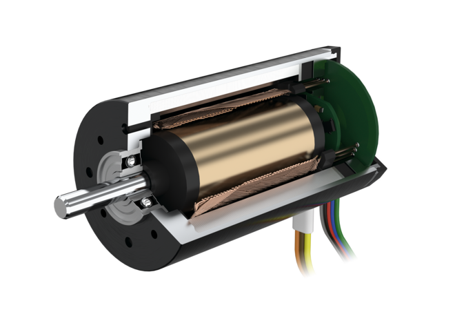
Motor Design and Configuration
The speed of a BLDC motor is fundamentally linked to its design. Several design elements, such as the number of poles, the winding layout, and the rotor structure, directly affect its speed.
Number of Poles
The motor’s rotational speed is influenced by its number of poles. In general, motors with fewer poles operate at higher speeds, while motors with more poles provide higher torque at lower speeds.
| Number of Poles | Speed (RPM) | Torque (Nm) |
| 2 | 10,000 | 0.5 |
| 4 | 5,000 | 1.0 |
| 6 | 3,000 | 1.5 |
| 8 | 2,000 | 2.0 |
As shown in the table, a motor with fewer poles can achieve a higher rotational speed (RPM), but torque increases as the number of poles rises.
Winding Configuration
The winding arrangement also determines the motor speed. There are typically two winding configurations in BLDC motors: Star (Y) and Delta (Δ).
- Star (Y) configuration provides higher torque but operates at lower speeds.
- Delta (Δ) configuration, on the other hand, allows for higher speed but provides less torque.
| Winding Configuration | Speed (RPM) | Torque (Nm) |
| Star (Y) | 3,000 | 1.5 |
| Delta (Δ) | 4,500 | 1.0 |
The Delta configuration enables the motor to operate at a higher speed but sacrifices some torque.
Supply Voltage
One of the most critical factors influencing BLDC motor speed is the supply voltage. The basic speed equation states that the supply voltage and motor speed are proportional.
Speed (RPM)∝Voltage (V)
Increasing the supply voltage will increase the motor’s speed, assuming all other conditions remain constant. There are restrictions on this, though, as high voltage might lead to motor damage or overheating.
| Voltage (V) | Speed (RPM) | Current (A) |
| 12 | 3,000 | 2.5 |
| 24 | 6,000 | 3.0 |
| 36 | 9,000 | 3.5 |
| 48 | 12,000 | 4.0 |
As shown in the table, doubling the voltage almost doubles the speed, making voltage a direct control factor for motor speed.
Controller Settings and Electronic Speed Control (ESC)
BLDC motors require an external electronic speed controller (ESC) for commutation and speed regulation. The motor’s voltage and current are managed by the ESC, which also modifies the motor speed. Several parameters within the ESC can influence motor speed:
- Duty Cycle: The ESC modulates the supply voltage through pulse-width modulation (PWM), and the duty cycle dictates how much time the voltage is applied within each cycle.
- Frequency of PWM: Higher frequency PWM signals result in smoother speed control and higher effective motor speeds.
| Duty Cycle (%) | Effective Voltage (V) | Speed (RPM) |
| 25 | 12 | 3,000 |
| 50 | 24 | 6,000 |
| 75 | 36 | 9,000 |
| 100 | 48 | 12,000 |
As the duty cycle increases, the effective voltage applied to the motor rises, resulting in an increase in motor speed.
Load and Torque Requirements
Another critical factor that influences the speed of a BLDC motor is the load it is driving. The relationship between speed and load is inversely proportional: as the load increases, the speed decreases.
Speed-Torque Curve
In BLDC motors, the speed-torque curve illustrates the relationship between these two variables. The motor speed drops as the load (torque) rises. The internal resistance of the motor and the reverse electromotive force (EMF) produced by the rotor are to blame for this.
| Torque (Nm) | Speed (RPM) |
| 0.5 | 10,000 |
| 1.0 | 8,000 |
| 1.5 | 6,000 |
| 2.0 | 4,000 |
| 2.5 | 2,000 |
The data clearly shows that as torque increases, the motor’s speed reduces proportionally. In real-world applications, it’s important to strike a balance between speed and torque requirements based on the load conditions.
Temperature
The operating temperature of a BLDC motor can also influence its speed. Motors become less efficient at higher temperatures due to increased resistance in the windings and other components, which can reduce speed.
Temperature-Speed Relationship
As temperature increases, the resistance of the windings increases, leading to a voltage drop that limits the available speed.
| Temperature (°C) | Speed (RPM) | Current (A) |
| 25 | 10,000 | 4.0 |
| 50 | 9,000 | 4.2 |
| 75 | 8,000 | 4.5 |
| 100 | 6,000 | 4.8 |
The table shows how a rise in temperature gradually reduces the motor speed. It’s essential to maintain proper cooling systems or avoid overloading the motor to ensure maximum speed and efficiency.
Back EMF
Back electromotive force (back EMF) is the voltage generated within the motor as it spins. The magnitude of this EMF, which is in opposition to the supply voltage, is determined by the motor’s speed. The faster the motor rotates, the higher the back EMF, which reduces the effective voltage available to drive the motor.
The back EMF constant, KeK_eKe, represents the voltage generated per unit of speed, expressed in V/rpm. The back EMF equation is:
Vemf=Ke×Speed (RPM)
For high-speed applications, the back EMF must be minimized to avoid excessive voltage loss, and motors with low back EMF constants are preferred.
Mechanical Constraints
Lastly, mechanical factors such as friction, bearing condition, and overall system inertia can also influence motor speed. Well-lubricated bearings and low-friction environments allow the motor to maintain higher speeds under load. Conversely, worn-out bearings or high-friction environments can drastically reduce the motor’s speed.
Conclusion
A BLDC motor’s speed depends on various factors, including the motor design, supply voltage, load, temperature, and the characteristics of the controller. As a brushless DC motor manufacturer, users can efficiently regulate and enhance the motor’s performance for particular applications by being aware of these dependencies.