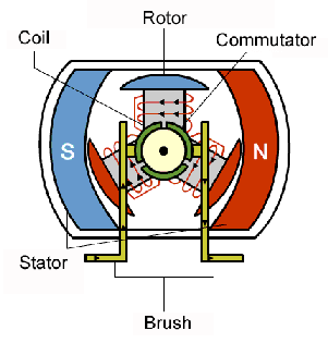
The Structure of Brushless DC Motor

Rotor
- Permanent Magnets: The rotor of a BLDC motor contains permanent magnets, typically made of rare-earth materials like neodymium, arranged around its circumference.
- Magnet Poles: The rotor can have multiple poles (e.g., 2-pole, 4-pole), which affect the motor’s torque and speed characteristics.
- Position (Outrunner vs. Inrunner): In an Outrunner motor, the rotor surrounds the stator, providing more torque. In an Inrunner motor, the rotor is inside the stator, which generally results in higher speeds.
Stator
- Wound Coils: The stator consists of windings made from copper wire, forming a series of electromagnets. These coils are placed in a certain configuration to produce the magnetic field that interacts with the rotor.
- Number of Phases: Most BLDC motors have a three-phase stator (three sets of coils), but they can also have more phases depending on the application.
- Core Material: To cut down on eddy current losses and boost efficiency, stator cores are frequently composed of laminated steel.
- Slots and Teeth: The stator has slots where the windings are placed and teeth to help direct the magnetic field generated by the coils.
Electronic Speed Controller (ESC)
- Control Unit: The ESC is an external device (but integral to the motor’s operation) that manages the current flowing through the stator coils. It performs the role of commutation by electronically switching the phases to keep the motor rotating.
- Pulse Width Modulation (PWM): ESC modifies the duty cycle of the PWM signal transmitted to the motor in order to modify its speed.
Bearings
- Supports the Rotor: Bearings are located at both ends of the motor to support the rotor shaft and allow smooth rotation. Superior quality bearings are essential for lowering friction and extending the motor’s life.
- Lubrication: Proper lubrication in the bearings helps in smooth operation and reduces wear and tear.
Housing/Frame
- Encloses and Protects Components: The motor’s housing or frame holds the stator and rotor in place and protects the internal components from dust, debris, and environmental conditions.
- Cooling: Some housings are designed to improve cooling, either passively through vents or with built-in fans.
End Bells (End Caps)
- Structural Support: The end bells are attached to both ends of the motor to hold the bearings and provide structural support. They also help protect the motor’s internals.
Working Principle of Brushless DC Motor
The working principle of brushless DC motor is different from that of traditional DC motor. It realizes brushless drive through electronic commutation, thus eliminating the carbon brushes and commutator in traditional DC motor.
The following is a detailed explanation of the working principle of brushless DC motor:
- Motor structure: The brushless DC motor is mainly composed of a stator, a rotor and a position sensor. The motor’s fixed part is the stator, which is often composed of many windings. The motor’s rotor, which is in rotation, is often constructed of permanent magnet material.
- Electronic commutation: In a brushless DC motor, an electronic commutator replaces the traditional mechanical commutator. The electronic commutator controls the direction of the current in the motor windings through a control circuit, thereby achieving continuous rotation of the motor.
- Position sensor: The rotor’s position is managed by the electronic commutator, which also modifies the current’s direction when necessary. The position sensor gathers this information. Common position sensors include Hall sensors, photoelectric sensors, and magnetoelectric sensors.
- Control strategy: The control strategy of brushless DC motors usually adopts vector control or trapezoidal control. Vector control achieves precise control of the motor by controlling the amplitude and phase of the current, while trapezoidal control achieves basic control of the motor by controlling the switching of the current.
- Efficiency and performance: Due to the elimination of carbon brushes and commutators, brushless DC motors are more efficient, run more smoothly, have lower noise, and lower maintenance costs.
Brushless DC Motor Operation Diagram
The Types of Brushless DC Motors
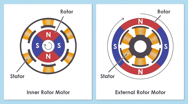
External Rotor Motor:
The stator is found inside the motor, but the rotor, which houses the magnets, is situated outside. Because of its design, torque may be increased at lower speeds by using a bigger rotor diameter.
These motors generally produce higher torque due to their larger rotor diameter, making them ideal for applications that require significant torque at lower speeds, such as drones, electric bikes, and model airplanes.
Inrunner BLDC Motors:
The stator surrounds the rotor, which is housed inside the motor housing. This design is more compact and typically results in higher speeds with less torque.
Inrunner motors are known for higher RPM (Revolutions Per Minute) and are more suitable for applications where high speed is essential, such as RC cars or small electric motors.
The following comparison chart:
| Feature | Outrunner BLDC Motors | Inrunner BLDC Motors |
| Rotor Position | Outside of the stator | Inside the stator |
| Torque | Higher torque per weight/size | Lower torque per weight/size |
| Speed | Generally lower speed | Generally higher speed |
| Efficiency | Slightly lower due to more moving parts | Higher efficiency due to less moving parts |
| Commutation | Electronic | Electronic |
| Startup Torque | Good startup torque | Requires higher speed to generate torque |
Brushless DC Motor Drive Mode
Six-Step Commutation (Trapezoidal Drive)
This is the most common drive mode for BLDC motors, where the motor is driven by three-phase voltage signals that are applied to the motor windings in a six-step sequence.
- Operation: In this mode, two phases are energized at a time, and the commutation occurs every 60 electrical degrees. This creates a trapezoidal back EMF waveform.
- Advantages: Simple to implement, cost-effective, and widely used in many applications.
- Disadvantages: Generates torque ripple, which can lead to noise and vibration, less smooth operation compared to sinusoidal drive.
Sinusoidal Drive
In this mode, the motor is driven with sinusoidal voltage waveforms instead of the trapezoidal waveforms used in six-step commutation.
- Operation: The sinusoidal drive creates a smoother transition between commutation steps, resulting in a more continuous and smooth torque output.
- Advantages: Produces smoother operation with less torque ripple, lower noise, and reduced vibration.
- Disadvantages: More complex and expensive to implement due to the need for precise control algorithms and higher resolution feedback.
Field-Oriented Control (FOC)
Also known as Vector Control, FOC is an advanced control technique that optimizes the efficiency and performance of the BLDC motor by controlling the motor currents in a rotating reference frame.
- Operation: FOC regulates the current in two perpendicular directions (d-axis and q-axis), aligning the motor’s magnetic field with the rotor’s position to maximize torque and efficiency.
- Advantages: Highly efficient, precise control over torque and speed, ideal for applications requiring smooth and accurate performance.
- Disadvantages: Requires complex algorithms and sophisticated hardware, making it more expensive and difficult to implement.
Direct Torque Control (DTC)
DTC is a method that directly controls the motor’s torque and magnetic flux without needing a coordinate transformation, often used in AC drives but can also be applied to BLDC motors.
- Operation: DTC uses a torque and flux estimator and applies voltage vectors to the motor to directly control the torque and flux.
- Advantages: Fast dynamic response, does not require precise rotor position information.
- Disadvantages: Can be more complex and may result in higher torque ripple compared to FOC.
Current Mode Control
This mode focuses on regulating the current through the motor windings rather than directly controlling voltage.
- Operation: To get the intended speed or torque, the motor controller modifies the current sent to the motor windings, frequently with the use of feedback loops.
- Advantages: Provides precise control over motor torque, good for applications requiring stable torque output.
- Disadvantages: More complex control system is required, the potential for slower response times compared to direct voltage control.
Sensorless Control
In sensorless control, the rotor position is estimated using the back EMF generated by the motor itself, eliminating the need for physical sensors.
- Operation: The controller estimates the rotor position based on the zero-crossing points of the back EMF, which is used to determine the appropriate commutation sequence.
- Advantages: Reduces the cost and complexity associated with sensors, and improves reliability by eliminating sensor failure points.
- Disadvantages: Can be less accurate, especially at low speeds where back EMF is weak, resulting in less precise control.
Sensored Control
Sensored control provides real-time feedback on the rotor position using Hall effect sensors or other position sensors.
- Operation: The sensors provide accurate rotor position data to the controller, which then adjusts the commutation sequence and timing accordingly.
- Advantages: Provides precise control over motor operation, excellent performance at low speeds and during startup, good for applications requiring high torque at low speeds.
- Disadvantages: Increases the cost and complexity of the motor system, potential reliability issues due to sensor failure.
Brushless DC Motor Selection Considerations
When selecting a brushless DC (BLDC) motor, several key considerations must be taken into account to ensure the motor meets the requirements of your specific application.
Power of BLDC Motor
Power (P)=Voltage (V)×Current (I)×Efficiency (%)×Power Factor (PF)
Consideration: Determine the maximum power required for your application, measured in watts (W).
Selection Tip: Choose a motor that can provide sufficient power to meet the peak load requirements. Ensure the motor’s continuous power rating is higher than the typical load and that the peak power rating can handle short bursts of higher demand.
Speed of BLDC Motor
Speed (RPM)=(Voltage (V)×Kv)/n
- Consideration: Identify the maximum speed (in revolutions per minute, RPM) needed for your application.
- Selection Tip: Select a motor that can achieve the desired maximum speed. Ensure that the motor’s speed range aligns with your application’s requirements, considering any gear reduction if necessary.
Voltage of BLDC Motor
V=Kv⋅RPM
- Consideration: Determine the operating voltage that will be used to drive the motor.
- Selection Tip: Select a motor that can run smoothly at the given voltage. Verify that the voltage and current required by the motor are compatible with your system and that your power source is capable of supplying them.
Size of BLDC Motor
- Consideration: Evaluate the physical size constraints, including the motor’s diameter, length, and shaft diameter.
- Selection Tip: Select a motor for your application based on how much room it will take up. Consider the motor’s mounting configuration and ensure that the shaft diameter is compatible with your mechanical setup, such as couplings or gears.
Hall Sensors: With or Without
Consideration: Decide whether the motor needs to have Hall sensors or not.
Selection Tip:
- With Hall Sensors: Choose a sensored BLDC motor if precise control at low speeds, smooth start-up, or accurate positioning is critical for your application. Hall sensors provide real-time feedback on rotor position, improving control.
- Without Hall Sensors: Opt for a sensorless BLDC motor if you need a simpler, more robust design where precise control at low speeds is less critical. Sensorless motors are typically less expensive and have fewer components.
Conclusion
For many different applications, a brushless DC motor is the best choice because of its great efficiency, dependability, and precise control. For a brushless DC motor manufacturer, its lack of brushes reduces maintenance, and its compact design delivers powerful performance. Understanding its components, operation, and benefits is key to optimizing its use in modern engineering solutions.