コアレスDCモーターは、軽量、低慣性、高効率という特長から、幅広い業界で広く採用されています。コアレスDCモーターの速度制御には、性能を最適化し、スムーズな動作を確保するために、綿密に設計された制御システムが必要です。
この記事では、コアレスDCモーターの速度制御方法について解説し、一般的な制御技術に関するデータを提供することで、様々なアプリケーションに適した制御方法の理解を深めます。
DCモーターの速度制御の基本原理
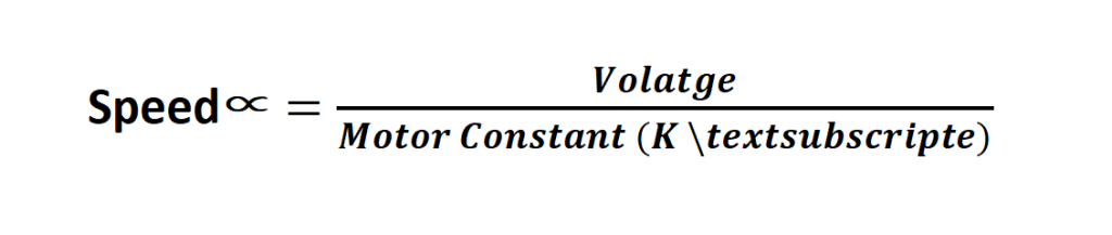
コアレスDCモーターを効率的に動作させるには、モーターの速度、電圧、電流、負荷の関係を理解することが重要です。DCモーターの速度は通常、印加電圧に比例します。
速度の管理に影響する要素は次のとおりです。
- 供給電圧 (V): 電圧を上げるとモーターの回転速度は上がり、電圧を下げると回転速度は下がります。
- 負荷トルク (T): 負荷が重いとモーターの回転速度は低下し、負荷が軽いとモーターの回転速度は上がります。
- 抵抗 (R): 回路内の抵抗は、内部抵抗でも外部抵抗でも、電流の流れに影響を与え、モーターの速度に影響を与えます。
- 逆起電力 (E): モーターが回転すると、入力電圧に逆らう逆起電力 (EMF) が発生し、全体の速度が低下します。
コアレスDCモーターの速度制御について
コアレスDCモーターの動作の基本的な考え方は、電気エネルギーを機械エネルギーに変換することです。モーターの速度は負荷に反比例し、印加電圧に直接関連します。したがって、モーターの速度を制御するには、供給電圧を調整するか、システム内の電流の流れを管理する必要があります。
コアレスDCモーターの速度に影響を与える主な要因は次のとおりです。
- 供給電圧 (V): 電圧を上げるとモーターの回転速度は上がり、電圧を下げると回転速度は下がります。
- 負荷トルク (T): 負荷が重いとモーターの回転速度は低下し、負荷が軽いとモーターの回転速度は上がります。
- 抵抗 (R): 回路内の抵抗は、内部抵抗でも外部抵抗でも、電流の流れに影響を与え、モーターの速度に影響を与えます。
- 逆起電力 (E): モーターが回転すると、入力電圧に逆らう逆起電力 (EMF) が発生し、全体の速度が低下します。
コアレス DC モーターの速度を制御する式は次のとおりです。
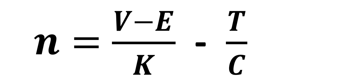
どこ:
- n = モータ回転速度 (RPM)
- V = 印加電圧 (V)
- E = 逆起電力 (V)
- k = モータ定数
- T = 負荷トルク (Nm)
- C = トルク定数 (Nm/A)
これらのパラメータを制御することで、モーターの速度を効果的に制御できます。
コアレスDCモーターの速度制御方法
コアレスDCモーターの速度制御にはいくつかの方法があり、それぞれに利点と限界があります。最も一般的な手法を確認してみましょう。
電圧制御(リニア制御)
電圧制御では、供給電圧を変化させることでモーターの速度を調整します。これは速度制御としてはシンプルな方法ですが、精度が低く、高出力アプリケーションでは効率が低くなります。
|
|
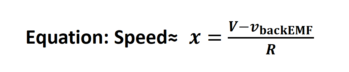
どこ:
- Vは供給電圧です。
- 逆起電力はモーターの回転時に発生する電圧です。
- Rはモーターの抵抗です。
電圧制御方式のデータ:
| 電圧 (V) | 回転速度 (RPM) | 効率 (%) |
| 6 | 1,500 | 85 |
| 9 | 2,300 | 88 |
| 12 | 3,000 | 90 |
| 15 | 3,750 | 92 |
| 18 | 4,500 | 93 |
上の表に示すように、電圧を上げるとモーターの速度は比例して上昇しますが、モーターが最大定格速度に達すると、この方法の効率には限界があります。
b. パルス幅変調(PWM)
パルス幅変調(PWM)は、コアレスDCモーターの速度制御において、より効率的で高精度な方法です。PWMは、一定の電圧を供給するのではなく、オン時間の長さ(デューティサイクル)を調整しながら、モーターのオン/オフを高速に切り替えます。この変調信号は、モーターの平均電圧を効率的に制御し、結果として速度を制御します。
デューティサイクルは、供給される平均電圧を決定し、次のように計算されます。

どこ:
- Vavg = 平均電圧
- Vin = 入力電圧
- D = デューティサイクル(%)
例えば、入力電圧が12Vでデューティサイクルが50%の場合、モーターに供給される平均電圧は6Vです。
|
|
PWM制御方式のデータ:
| デューティ比 (%) | 平均電圧 (V) | 回転速度 (RPM) |
| 20 | 2.4 | 1,000 |
| 40 | 4.8 | 2,000 |
| 60 | 7.2 | 3,000 |
| 80 | 9.6 | 4,000 |
| 100 | 12 | 5,000 |
表に示すように、デューティサイクルを上げると平均電圧が上昇し、モーターの速度もそれに比例して上昇します。
c. 電流制御
電流制御は、コアレスDCモーターの速度を調整するもう1つの方法です。この方法では、モーターに供給される電流を制御し、トルクと速度に直接影響を与えます。この技術は、ロボットや医療機器など、トルク管理と速度制御が必要な業界で広く使用されています。
|
|
電流制御法に関するデータ:
| 電流 (A) | 回転速度 (RPM) | トルク (Nm) |
| 0.5 | 1,000 | 0.1 |
| 1.0 | 2,000 | 0.2 |
| 1.5 | 3,000 | 0.3 |
| 2.0 | 4,000 | 0.4 |
| 2.5 | 5,000 | 0.5 |
3. 速度フィードバックシステム
より高度な用途では、コアレスDCモーターはフィードバックシステムと組み合わせて閉ループ速度制御を実現することがよくあります。一般的な方法は、モーターの速度をリアルタイムで監視し、入力パラメータを調整して所望の速度を維持するエンコーダを使用することです。
a. エンコーダを用いた閉ループ制御
- エンコーダ:モーターの位置または速度を検出するセンサーです。エンコーダからのフィードバックはコントローラに送られ、コントローラは入力電圧または電流を調整してモーターを所定の速度で回転させます。
フィードバックループは、特に負荷や入力電圧が変動する状況において、速度の一貫性を維持するために不可欠です。
b. 比例・積分・微分(PID)制御
閉ループシステムでは、モーターの速度性能を向上させるために、一般的にPID制御器が用いられます。PID制御器は、目標速度と実際の速度(誤差)の偏差に応じて、リアルタイムで調整を行い、モーターの速度を変化させます。
- 比例(P):現在の誤差を修正します
- 積分(I):過去の誤差を時間経過に沿って合計することで修正します
- 微分(D):変化率に基づいて将来の誤差を予測します
コアレスDCモーターのPID制御データ:
| 時間 (s) | 設定速度 (RPM) | 実際の速度 (RPM) | 誤差 (RPM) |
| 0 | 3,000 | 2,800 | 200 |
| 1 | 3,000 | 2,900 | 100 |
| 2 | 3,000 | 3,000 | 0 |
| 3 | 3,000 | 3,000 | 0 |
表に示すように、PIDコントローラは誤差を徐々に低減し、2秒以内に目的の速度に到達します。
速度制御方式の比較概要
| 制御方式 | 複雑さ | 効率 | コスト | 応用例 |
| 電圧制御 | 低い | 中程度 | 低い | 単純なアプリケーション、低精度機器 |
| PWM制御 | 中程度 | 高い | 中程度 | ロボット、ドローン、自動車、精密機器 |
| 電流制御 | 高い | 低い | 高い | トルク重視の用途、ロボット |
| PID+エンコーダ | 非常に高い | 非常に高い | 高い | 高精度機器、医療機器 |
結論
コアレスDCモーターの速度制御には、用途、電力要件、制御精度に基づいて適切な方法を選択する必要があります。正確な速度制御と応答性が重要なアプリケーションにおいて、Gian Transimissionは最も信頼性の高いソリューションを提供します。