Brushless DC (BLDC) motors are becoming more and more well-liked because of their smooth torque delivery, high efficiency, and dependability. Among these, three-phase BLDC motors are widely used in applications ranging from industrial equipment to electric vehicles and drones. Wiring a three-phase BLDC motor correctly is critical for its optimal operation and longevity. This article will guide you through the essentials of three-phase BLDC motor wiring, step-by-step instructions, and best practices.

A Three-phase BLDC Motor Consists of
- Rotor: Permanent magnets that rotate.
- Stator: Stationary windings in three phases—labeled as A, B, and C.
- Electronic Speed Controller (ESC): Transforms DC power into motor-specific three-phase AC power.
The motor is powered by three-phase currents that are 120° out of phase. A constant torque is generated by the interaction of these currents with the rotor’s magnetic field.
Components Needed for Wiring
Before wiring a three-phase BLDC motor, ensure you have the following components:
- Three-phase BLDC motor
- Electronic Speed Controller (ESC)
- Power source (battery or power supply)
- Hall sensors (optional, for closed-loop control)
- Wires (appropriately gauged for current ratings)
- Connectors (e.g., bullet connectors or screw terminals)
Step-by-Step Guide to Wiring
Identify Motor Phases
The motor will have three wires corresponding to its three phases. These are typically color-coded (e.g., yellow, green, and blue). If not labeled, refer to the manufacturer’s datasheet or use a multimeter to test the coil continuity.
Connect Motor Phases to ESC
The ESC also has three output terminals (usually color-coded) to match the motor phases. Connect:
- Motor phase A → ESC output A
- Motor phase B → ESC output B
- Motor phase C → ESC output C
There is no strict polarity for initial wiring, as the ESC can adapt to the wiring order.
Hall Sensor Wiring (if applicable)
If your motor has Hall sensors, connect the Hall sensor wires from the motor to the ESC. These wires typically include:
- Three signal wires: For sensors corresponding to phases A, B, and C.
- One power wire: Supplies power to the sensors (commonly 5V or 3.3V).
- One ground wire: Connects to the ESC ground.
Ensure that the Hall sensor connector matches the ESC pinout. If not, use a custom wiring harness.
Power Supply Connection
Connect the ESC’s power input terminals to the power supply or battery. Ensure:
- Polarity that is positive to positive or negative to negative is accurate.
- Voltage compatibility between the ESC and the motor.
Test Motor Direction
- Once wired, power on the system. Any two of the three motor phase wires can be switched if the motor is spinning in the wrong direction.
Common Wiring Configurations

Three-phase BLDC motors can be configured in two primary ways:
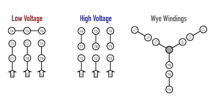
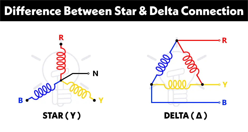
Wye (Star) Configuration
- A Y shape is formed by the connection of all three windings at a single point.
- The windings’ ends are connected to the controller’s U, V, and W terminals.
- Common in applications requiring higher torque at low speeds.
Delta Configuration
- The windings are connected end-to-end, forming a triangle.
- Each winding connects directly to two terminals of the controller.
- Preferred for applications demanding high speeds.
Comparison Chart: Wye vs. Delta Configuration
| Feature | Wye Configuration | Delta Configuration |
| Torque at Low Speed | Higher | Lower |
| Speed Range | Lower | Higher |
| Efficiency | Higher at low speeds | Higher at high speeds |
| Current Requirements | Lower | Higher |
Common Wiring Diagrams
Basic Wiring Setup
An abridged wiring diagram for a three-phase BLDC motor without Hall sensors may be found below:
| Component | Connection |
| Motor Phase A | ESC Phase A |
| Motor Phase B | ESC Phase B |
| Motor Phase C | ESC Phase C |
| Power Supply Positive (+) | ESC Power Input Positive |
| Power Supply Negative (-) | ESC Power Input Negative |
Wiring with Hall Sensors
For Hall sensor-equipped motors, add these connections:
| Hall Sensor Wire | ESC Hall Sensor Input Pin |
| Hall Sensor A | Hall Input A |
| Hall Sensor B | Hall Input B |
| Hall Sensor C | Hall Input C |
| Power (+) | Hall Power Pin |
| Ground (-) | Hall Ground Pin |
Important Considerations
Ratings of Voltage and Current
Ensure that:
- The motor, ESC, and power supply are compatible in terms of voltage and current.
- Wires are sized correctly for the current to prevent overheating.
Insulation and Safety
- Use insulated connectors to prevent short circuits.
- Avoid loose wires that might come into contact with other components.
Grounding
- Proper grounding minimizes electrical noise and improves system reliability. Ensure the ground of the power supply, ESC, and Hall sensors are connected.
Troubleshooting Tips
If your motor does not run correctly, consider these potential issues:
| Problem | Possible Cause | Solution |
| Motor does not start | Incorrect phase wiring or loose connections | Recheck connections and continuity. |
| Incorrect direction of rotation of the motor | Phase sequence error | A motor’s phase wires can be switched. |
| Jerky or erratic movement | Faulty Hall sensor wiring or ESC configuration | Verify Hall sensor connections. |
| ESC overheating | Excessive current or incorrect motor parameters | Check load and ESC settings. |
Applications of Three-Phase BLDC Motors
- Electric Vehicles: Smooth torque and high efficiency make BLDC motors ideal for EVs.
- Drones and Robotics: Both fine control and lightweight.
- Industrial Equipment: Reliable and durable for demanding environments.
Conclusion
A three-phase BLDC motor’s longevity and performance depend on its wiring. Whether you’re using it in a high-speed industrial application or a precision-controlled drone, following the correct wiring procedures will ensure smooth operation. Always prioritize safety, consult your motor and ESC datasheets, and verify connections before applying power.
